


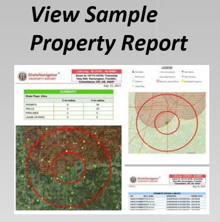
How to Measure Well Spacing on a Shale Development Map
Well spacing is a central consideration in shale development, mineral-rights analysis, and property research. The distance between producing wells can help reveal drilling density, possible infill activity, pad design, and how nearby development may affect a lease or tract.
An interactive map makes this analysis faster than estimating distances from a paper map or relying on inconsistent online measuring tools. With the right layers turned on, you can measure between well locations, compare spacing across a field, and record results that support leasing, engineering, title, or investment decisions.
The process is straightforward, but reliable results depend on selecting the correct wells, using consistent units, and understanding what the measurement represents. The map’s measuring tool is most useful when paired with permit, production, parcel, pipeline, and mineral-rights information.
Choose the Right Map View
Begin by opening Shale Navigator and locating the area, county, or shale play you want to study. Search by a known well, owner, township, county, or geographic location when possible. Starting with a recognizable reference point reduces the risk of measuring the wrong group of wells.
Turn on the well, drilling permit, and relevant shale-play layers before measuring. A permit point may represent a planned or authorized well rather than a completed producing well, while a well layer may include vertical, horizontal, plugged, and inactive locations. These distinctions matter when the goal is to evaluate current development or estimate future well density.
Use the map’s parcel and property layers when the measurement concerns a lease or tract. A well that appears close on the screen may sit across a boundary, road, or separate mineral estate. Measuring distance alone does not establish ownership, surface access, or the legal relationship between a well and a property.
Open and Configure the Measuring Tool
Look for the map control labeled with a ruler, measurement icon, or similar tool. Select the distance option rather than area if you are calculating well-to-well spacing. Depending on the map interface, the tool may allow you to choose feet, miles, meters, or kilometers. Select the unit most appropriate for the project and keep it consistent throughout the analysis.
Zoom in until individual well points are clearly separated. At a broad statewide or basin-wide view, several wells may overlap into a single symbol, making it difficult to select the intended location. A closer view also helps distinguish nearby laterals, surface locations, and permit points.
Click the first well location, then click the second. The tool should draw a line and display the calculated distance. If the interface supports additional points, avoid adding them unless you are measuring a route, lateral alignment, or multi-point pattern. For ordinary well spacing, a straight line between two selected locations is usually the clearest measurement.
Measure Center-to-Center Distance
Well spacing is generally described as the distance from one well location to another, measured center to center. Select the mapped point representing each well rather than the edge of a symbol, lease polygon, or pad outline. Symbols are often larger than the actual coordinate and can introduce errors when viewed at a low zoom level.
For horizontal wells, distinguish between surface-location spacing and lateral spacing. Two wells may have surface locations close together while their laterals diverge underground. Conversely, surface points may appear widely separated even though the laterals develop the same target formation. The measuring tool calculates the distance between the selected map coordinates; it does not automatically calculate subsurface drainage or lateral separation.
Measure several neighboring pairs instead of relying on one distance. For example, compare the first and second wells, the second and third wells, and wells on adjacent pads. A set of measurements can reveal whether spacing is regular, whether a pad contains multiple wells, or whether an apparent gap reflects undeveloped acreage rather than unusual geology.
Record the date, map layer, unit, well identifiers, and measurement value. Screenshots can preserve the visual context, while a spreadsheet can support later comparisons. This is especially helpful when permits and wells change over time or when a team needs to review the same analysis.
Compare Spacing With Development Data
A distance measurement becomes more meaningful when it is considered alongside well status and permitting activity. Compare producing wells with permitted locations to identify areas where the apparent spacing may tighten as development proceeds. A wide gap between producing wells does not necessarily indicate unleased or undeveloped acreage if additional permits are already active.
The Utica Shale overview provides useful context for examining county-level activity, permits, and development patterns. Regional differences in geology, operator strategy, infrastructure, and spacing rules can make a distance that appears unusual in one county relatively common in another.
Use pipeline and road layers to add operational context. A cluster of wells near gathering infrastructure may reflect access and economics rather than a simple spacing formula. Parcel boundaries and available mineral-rights data can also show whether a potential drilling pattern crosses multiple ownership interests.
| Measurement Task | Map Items to Use | What the Result Shows | Important Limitation |
|---|---|---|---|
| Well-to-well spacing | Well locations and distance tool | Straight-line distance between selected points | Does not describe underground drainage |
| Permit-to-well comparison | Permit and well layers | Potential future density or development sequence | A permit may be amended, delayed, or canceled |
| Pad spacing review | Well points, roads, aerial or property data | Relationship between surface locations and pads | Multiple wells may share one pad |
| Lease proximity | Well, parcel, and mineral-rights layers | Distance from development to a tract or interest | Proximity does not prove ownership or mineral control |
| Regional comparison | Shale-play, county, well, and permit layers | Differences in development density | Results may reflect different reporting dates |
Avoid Common Measurement Errors
The most frequent error is selecting a permit point when the analysis calls for an existing well, or selecting a well from a different formation. Confirm the record details before measuring. If several points overlap, zoom further in or temporarily hide unrelated layers so that the selection is unambiguous.
Another error is comparing measurements made at different scales or with different units. Feet may be appropriate for pad-level work, while miles may be easier for broad lease analysis. Convert values before comparing them, and avoid rounding until the final report. A distance of 1,320 feet, for example, should not be casually treated as one-quarter mile if precision matters.
Map accuracy also depends on the source data. Locations may be generalized, updated at different times, or tied to surface coordinates rather than the full well path. The tool is excellent for screening and comparative analysis, but legal descriptions, engineering designs, title opinions, and regulatory submissions may require authoritative records or professional verification.
Apply Measurements to Real Decisions
Landmen can use measured distances to prioritize leases near existing development or identify tracts surrounded by permits. Mineral-rights investors can compare development density across counties and evaluate whether a property sits near active drilling rather than only near historical wells. Engineers can use the map as an early screening tool before detailed subsurface modeling.
Attorneys, realtors, and landowners may also benefit from a visual explanation of nearby activity. A measured map can clarify whether a residence, tract, or lease lies close to a pad, pipeline, or planned well. It should support a broader review rather than replace title work, environmental diligence, setback analysis, or regulatory research.
Use the following practices for repeatable results:
- Confirm the formation, well status, and record date before selecting points.
- Measure center to center and keep the unit consistent across the project.
- Compare several neighboring wells instead of treating one distance as representative.
- Save screenshots and note the layers, zoom level, date, and selected records.
- Review permits, parcels, pipelines, and mineral-rights information alongside spacing.
A consistent workflow turns a simple map function into a useful development research record. It also makes it easier for another person to reproduce the analysis and understand why a particular spacing estimate was reported.
Build a Repeatable Mapping Workflow
For larger projects, create a standard measurement sheet with fields for county, play, operator, well names or identifiers, status, measured distance, unit, and source date. This allows results from multiple pads or leases to be compared without mixing surface spacing, lateral spacing, and permit spacing.
Consider measuring in several directions around a target tract. Distances to the nearest producing well, nearest permitted well, and nearest pad can answer different questions. A tract may be close to current production but farther from planned development, or it may sit beside a permitted pad that has not yet been drilled.
When the project requires additional records, account access, or help interpreting available map data, contact the Shale Navigator team. A free seven-day account can provide a practical way to test the mapping workflow, explore the available layers, and determine which subscription features fit ongoing research.
Open the map, select a clearly identified pair of wells, and record the first center-to-center distance. Then expand the review to nearby permits, parcels, pipelines, and mineral-rights information so the measurement supports a complete view of shale development activity.