


Estimating effective stimulated depths from public frac job records
How to estimate effective stimulated depths from public frac job records is a reconciliation exercise. A frac job sheet may show fluid and proppant, while a well file shows perforations; neither maps every fracture. Analysts combine depth references, location, stage design, pressure response and production evidence, then report a defensible interval and confidence level rather than a single exact number.
Effective stimulated depth is not automatically the deepest perforation, measured depth or fluid reach. In a horizontal well, measured depth increases along the lateral while true vertical depth changes little. A treatment can cover a long lateral yet contribute from a narrower vertical interval. State whether the estimate means deepest stimulated TVD, top-to-base thickness, or a representative depth for a reservoir model.
Australian users must translate US conventions. Records often arrive in feet, gallons, psi and acres, while Australian teams work in metres, hectares and Australian dollars and may need to reconcile US reporting dates with AEST or AEDT. The Bowen and Surat basins in Queensland, the Cooper Basin and the Perth Basin in Western Australia provide useful local context for comparing US shale records, but state tenure and environmental rules still govern any Australian project.
Reading public frac records
Begin by classifying the source. US records may come from FracFocus, a state oil and gas agency, an operator filing or a technical paper. Australian users can check completion reports from the relevant state petroleum authority and geological material from Geoscience Australia. Public releases vary: operator names, coordinates or stage details may be redacted, and a later revision can alter a reported volume. Save the publication date, revision date, well identifier and original unit with every imported record.
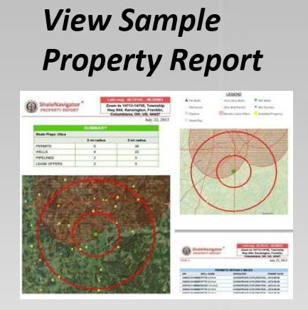
Extract API or well number, surface coordinates, casing and liner depths, perforations, lateral length, stage or cluster count, fluid types and volumes, proppant mass, treatment dates, pressure data, flowback and production information. Missing information is unknown, not zero. For spatial checks around a US well, interactive mapping can place permits, pipelines, lease offers, mineral-rights layers and property data near the documented location; it helps organise the evidence but does not measure fracture depth.
Establishing a reliable depth basis
Normalize every depth before comparing records. Distinguish measured depth (MD), true vertical depth (TVD), TVD below sea level (TVDSS), subsea depth, ground-level depth and elevation, and state the datum. Convert feet to metres by multiplying by 0.3048, keeping the original figure beside the converted one. Mixing MD with TVDSS can shift an interval by hundreds of metres, particularly where the wellhead is elevated or offshore.
For example, a record may list a deepest treatment point at 12,500 ft MD and an upper perforation at 11,300 ft MD. If a directional survey places them at 7,850 and 6,900 ft TVDSS, the gross interval is 950 ft, or about 290 m, not 1,200 ft. MD alone cannot establish TVD: each survey segment contributes its vertical component, calculated from MD and inclination. Without a deviation survey, build low, central and high scenarios and report the assumption rather than manufacturing precision.
Defining the effective interval
Define what “effective” means before assigning a number. Some teams use it for the deepest TVD with meaningful fracture initiation and proppant placement; others mean the vertical thickness, or true vertical length, between the upper and lower stimulated limits, or a representative depth for a reservoir model. Put that definition in the method note, because the same frac sheet can support different answers under each convention.
Start with the gross candidate interval, using the top and base of actual perforations or clusters, then check that it lies within the target formation and crosses the reservoir at a useful height. Stage spacing, skipped clusters, partial perforation and uneven proppant can weaken the case for treating the entire gross interval as effective. Where a report gives only a lateral length or one frac depth, use deviation and formation tops to bracket the interval, disclose the bracket and keep confidence attached to the result.
Weighing stimulation evidence
Direct evidence includes cluster maps, perforation logs, fibre-optic temperature or strain data, microseismic surveys and pressure charts showing breakdown, closure or frac gradient. Public job records often contain only part of this set, so indirect evidence matters: flowback volume and rate, shut-in pressure, proppant concentration, treatment pressure, early production and decline behaviour. Each signal has limits; production alone cannot prove a fracture height, and microseismic event clouds show where energy was detected rather than the full conductive network.
A practical estimate can retain the gross interval as an upper bound and report a narrower working interval when only some stages have documented injection, adequate proppant or sustained flowback. Fluid and proppant per metre, stage completeness and pressure response help justify that choice. For the illustrative well above, 6,900–7,850 ft TVDSS is the gross interval; 6,950–7,750 ft TVDSS could be a working range if the evidence supports narrower coverage. Give the result as a range with a high, medium or low confidence label, and state whether confidence reflects source quality, depth control or stimulation evidence. A modelled stimulated reservoir volume (SRV) is another output, but its boundary depends on the monitoring assumption and should not be mistaken for a direct depth measurement.
Checking rights and Australian context
A parcel screen is separate from a depth estimate. Surface ownership, subsurface mineral rights, a lease, a royalty obligation and a drilling permit may be held under different documents or by different parties. The property search facts guide explains how property records and mineral-rights information can be used as screening clues. Treat a mapped interest as a lead for title review, never as proof that the owner controls shale, oil or gas at a particular TVD.
In Australia, petroleum and mineral tenure are administered through state and territory legislation, with land access, water, heritage and native-title processes layered on top. Queensland’s Coal Seam Gas Production and Methane Management Act 2011 shows how access and methane-management duties can be separated, but its provisions do not automatically govern a shale well. In a Brisbane or Perth land review, teams often cross-check state land-valuation portals, council planning maps and tenement registers before involving local land professionals, attorneys and title officers. Australian public data may be less detailed than US frac disclosures, so preserve assumptions when transferring a US methodology to the Bowen, Cooper or Perth Basin.
A practical estimation workflow
Keep the workflow repeatable by separating source capture, depth normalization, geological screening, stimulation evidence and reporting. The following checks are suitable for a desktop study or a due-diligence file:
- Create a well register with identifiers, coordinates, operators, sources, dates, units and revision history.
- Convert MD, TVD and TVDSS consistently, document the survey used and flag records with no reliable deviation control.
- Draw gross and candidate effective intervals from verified perforations or clusters, not from total lateral length alone.
- Attach evidence to each interval, including stage completeness, proppant, pressure, logs, flowback and production, and assign a confidence level.
- Publish a range with assumptions, uncertainties and a clear definition of effective stimulated depth.
Store the raw record beside the cleaned values and the final estimate. That audit trail lets a geologist, landman or lawyer review the same result without confusing a treatment volume, a geometric depth and a stimulated reservoir thickness.
Australian operators can apply the same discipline to US reference data while using local registries for land and tenement decisions. Shale Navigator’s mapping layers, play context and property information help teams compare locations and organise due diligence before field interpretation.
Create a free seven-day Shale Navigator account, compare its play, permit, pipeline, mineral-rights and property layers, then review subscription options for any deeper data your due diligence requires.